


This robot competed in the 2016 Sample Return Robot Challenge, a yearly robotics challenge sponsored by NASA. I was responsible for designing the sensor mounts and the electronics enclosure, and I contributed to the design of the end effector. In addition to my duties as a mechanical designer, I assisted our software team with their testing procedures.
This electronics enclosure was designed with the needs of the electrical and software subteam's needs in mind. Our electrical lead expressed a need for copious ventilation and the ability to easily reposition components in the enclosure as their design evolved.
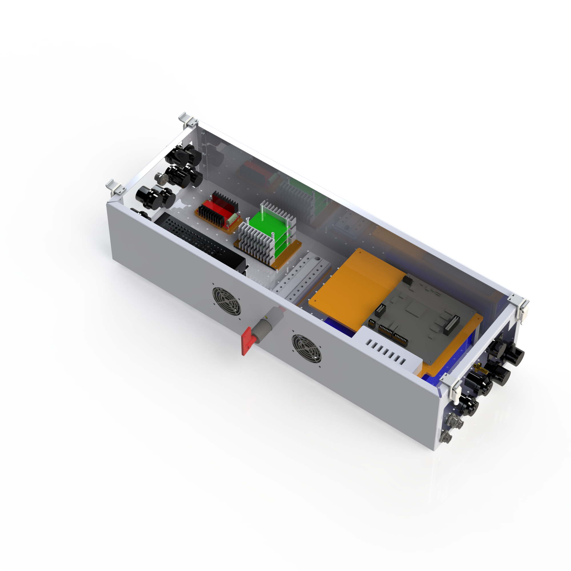
To accommodate both of these requirements, I designed the sheet metal enclosure with a uniform matrix of holes in the bottom. The holes were sized to fit M3 screws. The electrical components were mounted to acrylic plates, which were themselves mounted to standoffs that were screwed to the bottom of the enclosure from the outside. The matrix of holes improved air flow, and made it possible for the electrical and software teams to "play Tetris" with the components as their design changed over the course of the year.
This modular approach to mounting components worked so well and our team was so pleased with it that it was the only design idea that the following year's rover kept from the 2015-2016 rover.
This is a side view of all of the sensor mounts I designed for the robot, as well as a view of the end effector I helped design. At the very top looking over the end effector was a webcam looking down at the sample collection area. This provided input to our CV system to tell the end effector where it needed to move in order to pick up the sample. To the left of that camera we have two stereo cameras, one on top of the other. One camera was used for terrain mapping and localization and the other was used to seek and find the color coded samples. Finally, below those two camera mounts at the very base of the aluminum extrusion was our optical flow camera, which is not pictured in this render.
I was given numerous constraints for my mounts, all of which I was able to work with to produce functional, satisfactory results. First, all of the enclosures needed to be 3D-printable. This was mainly to reduce cost (the OSU Robotics club had access to free PLA). Our team lead also asked that we use 2020 aluminum extrusion to mount the enclosures to the robot's frame. This was to make the enclosures easy to reposition on the fly, as we could just mount them at any point on the extrusion's slot and slide them around as needed.